Tuesday, February 24, 2015

Electron Cont'd (9)

We're now ready to discuss some results from our JSBSim flight dynamics simulation. In this post, we'll talk mainly about how to survive maximum aerodynamic pressure, or max q.
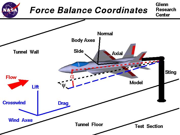
Let's begin by defining the coordinate systems used for our rocket, as well as major forces and velocities involved.


The engines produce a forward thrust that pushes the rocket along the direction of velocity V. Most liquid rocket engines require a little bit of time to develop enough thrust to be able to lift the combined mass of the rocket plus fuel and oxidizer off the ground. During this short period, a hold down mechanism is typically used to keep the rocket stable on the pad. While the rocket is flying within the atmosphere, a drag force due to air resistance (wind) directly opposes the rocket's thrust.

If the rocket's velocity vector is not aligned with the actual pitch angle with the horizon, the resulting angular difference is called the angle of attack alpha. A large alpha may result in a strong perpendicular lifting force due to aerodynamic lift. This is usually bad, because for a long object such as a rocket, excessive perpendicular forces could cause the rocket to bend and result in structural failure. Thus many rockets aim to fly a zero angle of attack and throttle back during flight through max q. This reduces bending forces to a manageable extent.

The following Octave (Matlab) plots of a JSBSim run demonstrate the gravity turn maneuver in terms of pitch angle variation with time (left) and angle of attack (right). A 90-degree pitch angle means "vertical" and 0-degrees is "horizontal". Dynamic pressure appears as peaks in both plots.

Notice how the gravity turn drops the angle of attack to zero just before peak dynamic pressure. We're also throttling back all main engines to 75% at MET+79 and throttling up again at MET+129. To show how bad things would be like without these countermeasures, here is another JSBSim run, but with no engine throttling and the gravity turn approximated by a straight line. Max q is now about 66% greater (500 psi), and the angle of attack nearly hits 7 degrees (as a rule of thumb, most launch vehicles try not to go beyond 4 degrees while passing through max q):

At this point, it is important to note that zero alpha is not a panacea. In fact, zero alpha must not (and does not have to) be maintained throughout the whole flight. This is because sticking to such a flight profile can result in excessive pitchover, and penalties in altitude gain later in flight (see for example: Turner, 2006. Rocket and Spacecraft Propulsion: Principles, Practice and New Developments). So we switch to a lower rate of pitchover as soon as we can (once the rocket passes max q). This allows the rocket to gain altitude more quickly. The following plot illustrates this nicely. Apart from revealing that our rocket has come a long way since our initial experiments and is now able to reach altitudes >1,500,000 ft (>450 km!), notice how the altitude line becomes steeper after passing through the gravity turn phase, indicating that the rocket is able to gain altitude quicker:


Sideways winds gives rise to side forces that causes the rocket to yaw (swivel and spin sideways). Left unchecked, this can result in oscillations that lead to destabilization and tumbling (as we saw in our earlier experiments with OpenRocket). Thus we have also added controllers for holding the yaw rate steady by actuating the first and second stage engines.

In verifying the performance of our yaw and pitch control, it is useful to look at the 3 different components u, v, w of the total velocity V:
  • u: Velocity directly along the axis of the rocket ("forward")
  • v: Sideways velocity
  • w: Vertical velocity
Our aim is, by the end of our launch trajectory, eventually maximize u, and make v (yaw) and w as small as possible—in a circular orbit, u would be a constant orbital velocity and v, w should be zero.

To be continued...

Electron Cont'd (8)

Let's talk launch trajectory design.
The basic steps included in many orbital launch profiles are the following:
  1. Vertical Launch: Pitch angle (angle from horizontal)=90 degrees
  2. Pitchover Maneuver: Rocket is tilted slightly and so is no longer vertical, initiating the gravity turn
  3. Gravity Turn: Rocket pitch angle is increased so that the rocket flies a curved path and the angle of attack is nearly zero, minimizing aerodynamic stresses at the expense of not gaining altitude as rapidly
  4. Max Q Throttling: Engines are throttled down while passing through maximum dynamic pressure ("Max Q") to reduce aerodynamic stresses; usually happens at around 70 seconds into flight just prior to hitting the sound barrier
  5. Engine Cut-Off: Often abbreviated to MECO when referring to main engine cut-off, engines are shut down once fuel is used up and thrust falls below a certain level, or deliberately to coast
  6. Staging: Stages that have spent fuel are jettisoned to reduce mass
  7. Payload shroud (fairing) Jettison: Shroud protecting the payload at the top of the rocket is jettisoned early to reduce mass once altitude is high enough and air is thin enough
  8. Payload/Upper stage Deployment: Payload is deployed by mechanical means (e.g., springs) or given a boost to a different orbit by an upper stage kick motor
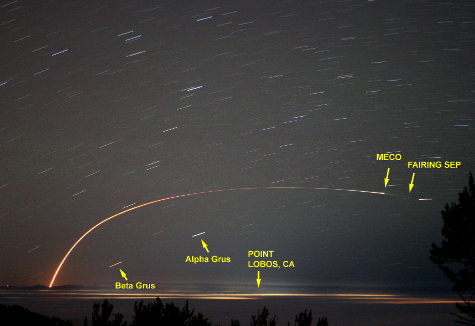
Here is a great long-exposure photograph of the OCO-2 launch by Rick Baldridge illustrating the entire launch flight path including the characteristic curvature of the gravity turn. (Visit the web page to learn more)


Some rockets may also perform a Roll program during launch to roll the rocket to a certain orientation about its central axis. For example, the Space Shuttle rolled over to make sure its wings faced up during the gravity turn and reduce aerodynamic loads. Here is a gif illustrating it from NASA TV coverage of STS-129:


Continue reading...

Electron Cont'd (7)

I sent an email to Rocket Lab last week asking about the upper stage.
I addressed the email to the general media inquiry address at Rocket Lab, but imagine my surprise when the CEO replied personally!
From: Peter Beck <email address redacted>
Date: Fri, Jan 30, 2015 at 7:51 AM
Subject: Rocket Lab

Hi Dawoon,

Nice work!

It's no fun if we answer all your questions, but you are on the right track......

Pete

--
Peter Beck
CEO

ROCKET LAB LTD.

Apart from the fact that it was very cool to get a personal email from the head of a rocket company and that we know that we're on the right track, let's recap what our plan is so far.
On top of stage 2 is a hexagonal stand. There is a ring on top of this stand through which a upper stage kick motor is inserted before launch. And on top of the upper stage is the payload:


Christophe our designer decided to etch the big letters ELECTRON and the NZ logo onto the rocket instead of using textures.
While this turned out to be much more challenging in terms of uv mapping, this allowed us to get very clean results even at high zoom without using huge textures:


Continue reading...

Electron Cont'd (6)

Let's take a break from aerodynamics, and see if we can improve the 3D model of Electron.
Christophe Campos has offered his designer skills and has done a much better job at creating a more detailed model of the rocket!
Notice details such as straps holding the tanks to the underside of the second stage, rivets on the bottom of the first stage, and cleaner textures:


The one remaining issue is the part joining the payload and the second stage. This is a closeup from Rocket Lab's web site:


The golden cube is definitely the payload, but Christophe and I can't figure out what the rest of the parts are.
The red outlined part below the payload is probably an upper stage kick motor (a rocket motor that would fire to boost the payload into its final orbit). But that's just a wild guess, and we don't know what the black hexagonal structure that is masking part of the upper stage(?) is. Is it part of the second stage? What are the tanks inside the hexagonal structure? etc.

Continue reading...

Electron Cont'd (5)

Aerodynamic coefficients are specified in the aerodynamics section in the aircraft definition file.
Coefficients must be defined per axis; for Electron, I specified DRAG (axial) and LIFT (pitch/normal) axes.
Normally, I would also need to define the SIDE (yaw) axis, but due to symmetry about the longitudinal axis, SIDE is simply equal to -LIFT.


DRAG force is a factor of the following:
  • Dynamic pressure (JSBSim property: aero/qbar-psf): pressure of air exerted on moving rocket; increases with speed
  • Cross-sectional area (JSBSim property: metrics/Sw-sqft): for a cylindrical rocket, equal to the circular cross sectional area
  • Angle of attack alpha (JSBSim property: aero/alpha-rad): angle between wind and rocket, related to pitch angle
  • Mach number (JSBSim property: velocities/mach)
RASAero was able to plot the drag coefficient CD versus alpha at Mach 0.1, 0.5, 1.1, 2.0, 5.0.
It was also able to plot CD versus Mach number from 0 to 25.
I defined tableData elements in JSBSim for these two plots. The first plot has two independent variables alpha and Mach number so the table is two-dimensional with alpha increasing from top to bottom, and Mach number increasing from left to right.
The second table is just CD with Mach number increasing from top to bottom. I took the "power-on" sim values (exhaust plume effects included) as the rocket will likely be thrusting through most of its flight path.


LIFT force, like DRAG, is also a factor of dynamic pressure, cross-sectional area, angle of attack, and Mach number.
I defined another two-dimensional table with independent variables alpha and Mach number from a RASAero plot of lift coefficient CL.


Next I will define the GNC parameters for stabilizing the rocket during flight.

Electron Cont'd (4)

JSBSim is an open source flight dynamics simulator. It can simulate the flight of balloons, gliders, prop planes, jets, rocket-powered jets, and rockets. Importantly, I can program in GNC (guidance, navigation, control) logic to perform active stabilization during flight. JSBSim is a console program that takes xml files as input and outputs csv files (which can be plot in Matlab or Excel), linked to Simulink, or even stream output via telnet for remote "telemetry."

A JSBSim model requires aircraft, engine, and script definitions.
This is how I structured the Electron flight model in JSBSim:
aircraft/
Electron.xml: Rocket geometry, aerodynamic parameters (from RASAero), and engine config
NZ01.xml: Parameters of (imaginary) launch site in New Zealand

aircraft/Systems/
ElectronControlSystem.xml: GNC parameters
ElectronGuidanceExecutive.xml: Mission clock, guidance modes
ElectronFirstStageEffectors.xml: First stage engine gimbal definition
ElectronSecondStageEffectors.xml: 2nd stage engine gimbal definition

engine/
Rutherford.xml
Rutherford-nozzle.xml
Rutherford_vac.xml
Rutherford_vac-nozzle.xml

scripts/
Electron.xml: Defines wind speeds, rocket staging, console output

I based the file organization and GNC structure on the Jupiter-246 concept model available in JSBSim, but otherwise everything was done nearly from scratch.

The masses of each major rocket part such as payload shroud, body tubes, engines, were specified as pointmass elements inside the mass_balance section of the aircraft definition, aircraft/Electron.xml. Only cylindrical and spherical (solid or hollow) shapes can be specified, so it ends up being an approximation of the geometry. The dimensions of each part are fairly well defined from Rocket Lab's web site, and I used masses previously estimated when trying OpenRocket.

Engines are first defined in engine files (the engine and nozzle are separately defined in JSBSim). Here are example engine and nozzle files for the Rutherford engine. The Isp was guessed from other high-performing Kerosene liquid engines, and the mass flow rate \(\dot{m}\) was calculated using the relation \(Isp=F/\dot{m}g\) where F is the thrust of the engine given on the Rocket Lab web site (146.6 kN peak, or 16.3 kN/engine) and g is the acceleration due to gravity 9.8 m/s^2. The mixture ratio 2.6 is a standard oxidizer to propellant mixture ratio for LOX/kerosene. Incidentally, LOX/Kerosene is the same proven combination used on the Saturn V moon rocket and SpaceX's Falcon 9.

<?xml version="1.0"?>
<rocket_engine name="Rutherford">
  <isp>                   350.0 </isp>
  <maxthrottle>           1.00  </maxthrottle>
  <minthrottle>           0.40  </minthrottle>
  <propflowmax unit="LBS/SEC"> 10.4625 </propflowmax>
  <mixtureratio> 2.6 </mixtureratio>
</rocket_engine>


<?xml version="1.0"?>
<nozzle name="Rutherford Nozzle">
  <!-- area = Nozzle exit area, sqft. -->
  <area unit="FT2">  0.209  </area>
</nozzle>


This NASA web site gives a nice introduction to the concept of specific impulse.

Tanks are specified in the aircraft definition file, by giving the types (FUEL/OXIDIZER), locations, capacities, and drain locations. Tanks are "hooked up" to engines by specifying the tank number as feed elements in each engine.

Continue reading...

Electron Cont'd (3)

JSBSim still requires that I specify aerodynamic data before I can realistically simulate atmospheric flight. These could be the following:

  • Drag coefficient for different Mach numbers (CD)
  • Side force coefficient (CY, or alternatively, normal force coefficient CN since a rocket is symmetric about its center)
  • Lift force coefficient (CA)

Normally, one would need to go about building a scale model and run a CFD sim or perform measurements in a hypersonic wind tunnel. However, I found a free program (unfortunately Windows-only, with no source code) called RASAero that can calculate various aerodynamic parameters through a wide range of Mach numbers in the specific case of a rocket with a nose cone and fins.

The following is the main screen of the program where I input the dimensions of the Electron rocket. As there are no fins on Electron, I set 0.0001 for the fin dimensions (since setting them to 0.0 would cause an exception). Also the program can display a sketch of the rocket:


This is an example of the plot output of drag coefficient versus airspeed (Mach number). You will notice the drag increasing dramatically just before Mach 1 (speed of sound). This illustrates the "sound barrier" nicely. There are two graphs: power-off is a simulation for gliding (unpowered) flight and power-on includes effects from the engine such as the rocket exhaust plume.


The next step is to copy and paste numbers from RASAero into JSBSim.

Continue reading...