Tuesday, February 24, 2015

Electron Cont'd (5)

Aerodynamic coefficients are specified in the aerodynamics section in the aircraft definition file.
Coefficients must be defined per axis; for Electron, I specified DRAG (axial) and LIFT (pitch/normal) axes.
Normally, I would also need to define the SIDE (yaw) axis, but due to symmetry about the longitudinal axis, SIDE is simply equal to -LIFT.
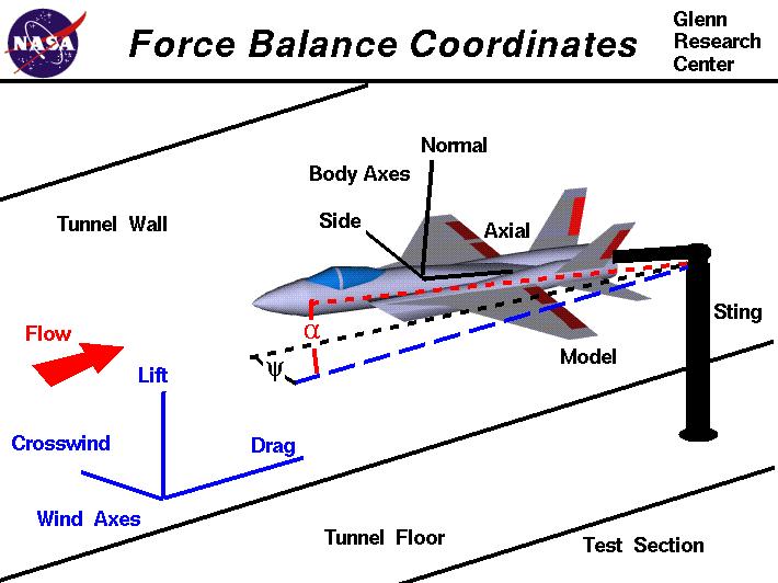


DRAG force is a factor of the following:
  • Dynamic pressure (JSBSim property: aero/qbar-psf): pressure of air exerted on moving rocket; increases with speed
  • Cross-sectional area (JSBSim property: metrics/Sw-sqft): for a cylindrical rocket, equal to the circular cross sectional area
  • Angle of attack alpha (JSBSim property: aero/alpha-rad): angle between wind and rocket, related to pitch angle
  • Mach number (JSBSim property: velocities/mach)
RASAero was able to plot the drag coefficient CD versus alpha at Mach 0.1, 0.5, 1.1, 2.0, 5.0.
It was also able to plot CD versus Mach number from 0 to 25.
I defined tableData elements in JSBSim for these two plots. The first plot has two independent variables alpha and Mach number so the table is two-dimensional with alpha increasing from top to bottom, and Mach number increasing from left to right.
The second table is just CD with Mach number increasing from top to bottom. I took the "power-on" sim values (exhaust plume effects included) as the rocket will likely be thrusting through most of its flight path.


LIFT force, like DRAG, is also a factor of dynamic pressure, cross-sectional area, angle of attack, and Mach number.
I defined another two-dimensional table with independent variables alpha and Mach number from a RASAero plot of lift coefficient CL.


Next I will define the GNC parameters for stabilizing the rocket during flight.

Electron Cont'd (4)

JSBSim is an open source flight dynamics simulator. It can simulate the flight of balloons, gliders, prop planes, jets, rocket-powered jets, and rockets. Importantly, I can program in GNC (guidance, navigation, control) logic to perform active stabilization during flight. JSBSim is a console program that takes xml files as input and outputs csv files (which can be plot in Matlab or Excel), linked to Simulink, or even stream output via telnet for remote "telemetry."

A JSBSim model requires aircraft, engine, and script definitions.
This is how I structured the Electron flight model in JSBSim:
aircraft/
Electron.xml: Rocket geometry, aerodynamic parameters (from RASAero), and engine config
NZ01.xml: Parameters of (imaginary) launch site in New Zealand

aircraft/Systems/
ElectronControlSystem.xml: GNC parameters
ElectronGuidanceExecutive.xml: Mission clock, guidance modes
ElectronFirstStageEffectors.xml: First stage engine gimbal definition
ElectronSecondStageEffectors.xml: 2nd stage engine gimbal definition

engine/
Rutherford.xml
Rutherford-nozzle.xml
Rutherford_vac.xml
Rutherford_vac-nozzle.xml

scripts/
Electron.xml: Defines wind speeds, rocket staging, console output

I based the file organization and GNC structure on the Jupiter-246 concept model available in JSBSim, but otherwise everything was done nearly from scratch.

The masses of each major rocket part such as payload shroud, body tubes, engines, were specified as pointmass elements inside the mass_balance section of the aircraft definition, aircraft/Electron.xml. Only cylindrical and spherical (solid or hollow) shapes can be specified, so it ends up being an approximation of the geometry. The dimensions of each part are fairly well defined from Rocket Lab's web site, and I used masses previously estimated when trying OpenRocket.

Engines are first defined in engine files (the engine and nozzle are separately defined in JSBSim). Here are example engine and nozzle files for the Rutherford engine. The Isp was guessed from other high-performing Kerosene liquid engines, and the mass flow rate \(\dot{m}\) was calculated using the relation \(Isp=F/\dot{m}g\) where F is the thrust of the engine given on the Rocket Lab web site (146.6 kN peak, or 16.3 kN/engine) and g is the acceleration due to gravity 9.8 m/s^2. The mixture ratio 2.6 is a standard oxidizer to propellant mixture ratio for LOX/kerosene. Incidentally, LOX/Kerosene is the same proven combination used on the Saturn V moon rocket and SpaceX's Falcon 9.

<?xml version="1.0"?>
<rocket_engine name="Rutherford">
  <isp>                   350.0 </isp>
  <maxthrottle>           1.00  </maxthrottle>
  <minthrottle>           0.40  </minthrottle>
  <propflowmax unit="LBS/SEC"> 10.4625 </propflowmax>
  <mixtureratio> 2.6 </mixtureratio>
</rocket_engine>


<?xml version="1.0"?>
<nozzle name="Rutherford Nozzle">
  <!-- area = Nozzle exit area, sqft. -->
  <area unit="FT2">  0.209  </area>
</nozzle>


This NASA web site gives a nice introduction to the concept of specific impulse.

Tanks are specified in the aircraft definition file, by giving the types (FUEL/OXIDIZER), locations, capacities, and drain locations. Tanks are "hooked up" to engines by specifying the tank number as feed elements in each engine.

Continue reading...

Electron Cont'd (3)

JSBSim still requires that I specify aerodynamic data before I can realistically simulate atmospheric flight. These could be the following:

  • Drag coefficient for different Mach numbers (CD)
  • Side force coefficient (CY, or alternatively, normal force coefficient CN since a rocket is symmetric about its center)
  • Lift force coefficient (CA)

Normally, one would need to go about building a scale model and run a CFD sim or perform measurements in a hypersonic wind tunnel. However, I found a free program (unfortunately Windows-only, with no source code) called RASAero that can calculate various aerodynamic parameters through a wide range of Mach numbers in the specific case of a rocket with a nose cone and fins.

The following is the main screen of the program where I input the dimensions of the Electron rocket. As there are no fins on Electron, I set 0.0001 for the fin dimensions (since setting them to 0.0 would cause an exception). Also the program can display a sketch of the rocket:


This is an example of the plot output of drag coefficient versus airspeed (Mach number). You will notice the drag increasing dramatically just before Mach 1 (speed of sound). This illustrates the "sound barrier" nicely. There are two graphs: power-off is a simulation for gliding (unpowered) flight and power-on includes effects from the engine such as the rocket exhaust plume.


The next step is to copy and paste numbers from RASAero into JSBSim.

Continue reading...

Electron Cont'd (2)

To simulate the atmospheric phase of an Electron launch, I tried using OpenRocket, a Java GUI originally designed for simulating model rocket launches.
However the limitations of using a model rocket simulator to simulate a 10.5-ton orbital launch vehicle quickly became apparent:


In the above screen, I roughly sketched out the two stages of the Electron vehicle using the measurements in my Blender model.
As Electron will use composite materials for its hull, I specified carbon fibre for my OpenRocket model as well.
There is no publicly available data on the thrust curve of the Rutherford engines powering the Electron, so I took the highest thrust motor O8000 available on ThrustCurve.org and scaled up the maximum thrust to match the peak thrust figure quoted for Rutherford on the Rocket Lab web site (146 kN for the 9-engine 1st stage cluster, or 16.2 kN/motor, and 18 kN for the 2nd stage vacuum motor). I also set the burn times for the engines to 114 seconds, which is about how long ESA's Vega burns for its 1st stage, and increased the propellant masses until the wet mass of the rocket was in the ballpark of the quoted figure of 10.5 metric tons.

This gets Electron up to about 1.6 km altitude and nearly Mach 0.4, but without active GNC (guidance, navigation and control), the LV starts to "dance" around and tumble out of control and hits the ground after only 70 seconds in the air. Here is a GNU Octave (Matlab) plot of the simulated flight profile from OpenRocket:


The problem is that all model rocket simulator programs like OpenRocket assume that you are using appendages such as fins to passively stabilize the rocket and cannot simulate active stabilization using a GNC system. Still, it's quite interesting to see how long such a large rocket can stay aloft even without stabilization.

To be able to simulate active control, a different program is required. Apparently JSBSim, which is also used by the open source flight sim FlightGear, allows you to model a rocket GNC system. This is not surprising, as the designer of JSBSim is Jon S. Berndt, who did rocket dynamics engineering work previously for NASA. My plan is to try this next.

Continue reading...

Electron

Here is a new addon I'm making of New Zealand's new Electron rocket (Disclaimer: I am not affiliated with Rocket Lab, the maker of Electron, and this endeavor is purely for fun).
Electron is a small rocket for launching 100 kg-class payloads to LEO: http://www.rocketlabusa.com
They're aiming to make their first launch in 2015, which if it succeeds would not only make New Zealand the 11th nation to perform an orbital launch with its own rocket, but would also start a trend of "smaller cheaper faster" in the launch industry.

Here is the full stack:


This is the 2nd stage (no payload yet):


All textures come from the Rocket Lab web site.
I used Blender for 3d modeling.
The aim is to model a full mission, such as a small spacecraft delivery to a translunar trajectory. I don't know if that's realistic though. I'm currently trying to get NASA's GMAT to compile on my Mac so that I can generate some interesting trajectories.

Continue reading...

This article was originally published on the Celestial Matters forum.

Friday, February 13, 2015

KARI Lunar Orbiter Cont'd (4)

While preparing this mission concept, I also took the opportunity to generate a fresh 32k normal map of the Moon using the latest 2014 LOLA data.
A previous version from 2011 is available from http://imbrium.mit.edu/EXTRAS/CELESTIA/ and also the Celestial Motherlode.

Like the 2011 version, I used LDEM_128.IMG from here: http://imbrium.mit.edu/DATA/LOLA_GDR/CYLINDRICAL/IMG/
Then I used Fridger Schrempp's nmtools to generate a DXT5nm virtual texture. I took the opportunity to compile nmtools again for the Mac in order to try out nmtilesDXT (a nmtools program that generates DXT5nm tiles). This worked, although I had to change the Makefile and also compile NVIDIA texture tools from scratch.

Anyway here is a side-by-side comparison of the original 2011 version vs the 2014 normal map generated by me:


As you can see, there is a clear improvement in quality in the 2014 data.
Details are sharper, and there are less artifacts as compared to the 2011 data. It goes without saying that the DXT5nm compressed format also saves disk space: 589 MB vs 946 MB for the 2011 version (which uses PNG).

KARI Lunar Orbiter Cont'd (3)

I think that the smoothed velocities are correct (i.e., the unsmoothed velocities with gaps are wrong).

Here is a plot comparing the smoothed and unsmoothed velocities of the spacecraft at launch time:

For both, the velocity profiles can be broken down into 3 main parts:

  1. Launch: Steep increase in velocity
  2. LEO orbit: Constant velocity (circular orbit)
  3. Trans-lunar Injection (TLI): Delta-v increase to push spacecraft towards the Moon

For the unsmoothed profile, the velocity evens out at only ~5.5 km/s, and the delta-v of TLI is only about +2 km/s.
These numbers are too small, especially considering that a typical orbital velocity of a circular LEO should be ~8 km/s.

By comparison, the smoothed profile flattens out at ~7.8 km/s, which is a reasonable velocity for LEO. Also, TLI delta-v is roughly +3 km/s, which is also in the ballpark for typical TLI delta-v's. :D

Continue reading...