The basic steps included in many orbital launch profiles are the following:
- Vertical Launch: Pitch angle (angle from horizontal)=90 degrees
- Pitchover Maneuver: Rocket is tilted slightly and so is no longer vertical, initiating the gravity turn
- Gravity Turn: Rocket pitch angle is increased so that the rocket flies a curved path and the angle of attack is nearly zero, minimizing aerodynamic stresses at the expense of not gaining altitude as rapidly
- Max Q Throttling: Engines are throttled down while passing through maximum dynamic pressure ("Max Q") to reduce aerodynamic stresses; usually happens at around 70 seconds into flight just prior to hitting the sound barrier
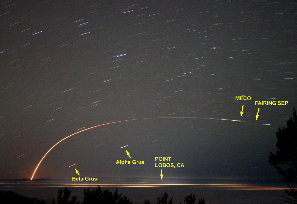
- Engine Cut-Off: Often abbreviated to MECO when referring to main engine cut-off, engines are shut down once fuel is used up and thrust falls below a certain level, or deliberately to coast
- Staging: Stages that have spent fuel are jettisoned to reduce mass
- Payload shroud (fairing) Jettison: Shroud protecting the payload at the top of the rocket is jettisoned early to reduce mass once altitude is high enough and air is thin enough
- Payload/Upper stage Deployment: Payload is deployed by mechanical means (e.g., springs) or given a boost to a different orbit by an upper stage kick motor
Some rockets may also perform a Roll program during launch to roll the rocket to a certain orientation about its central axis. For example, the Space Shuttle rolled over to make sure its wings faced up during the gravity turn and reduce aerodynamic loads. Here is a gif illustrating it from NASA TV coverage of STS-129:

Continue reading...
2 comments:
Hi.. good stuff on the Electron rocket here.. I'm looking to do a CFD optimization of the nozzle design for fun.. do you have any details about the rutherford engine and nozzle that could be useful? in particular, which nozzle geometry do they use? Is it the Rao optimized? what is the diameter and back-pressure?
Best Wishes,
Zac
Thanks for your interest!
I don’t have “insider” information unfortunately. I only used images publicly available on the website.
I used 1st stage nozzle radius = 0.258 ft = 7.8 cm, length 0.939 ft = 28.6 cm.
I am not an engine expert but by back pressure I guess you mean ambient air pressure?
JSBSim varies that with altitude according to 1976 Standard Atmosphere.
Post a Comment